
By Rayna Feng, Bill XU, Systems Engineering and Marketing, Texas Instruments
Currently, there are two methods to dim LEDs. In analog dimming methods, the current going through the LED is adjusted by an input control voltage. Digital (PWM) dimming, on the other hand, leverages the slow response of the human eye by quickly turning the LED on and off at a frequency above 100Hz without changing the LED current.
Most LED drivers have a PWM dimming input. However, the bandwidth of the LED driver limits the dimming frequency and contrast ratio. For a fixed-frequency switched-mode LED driver based on a DC/DC architecture, the loop bandwidth is typically set to 50kHz or less, limiting the contrast ratio to about 25:1 at a PWM frequency of 2kHz.
LED lighting in medical systems
Today, LED lighting is widely used in medical systems. The primary challenge in medical applications is the fact that only a limited number of LED drivers can output the large current required. Endoscope applications, for instance, may require up to 40A to compensate for the optical attenuation in the fibre. The second challenge is the requirement for a highly linear LED current without any ripple, especially in IVD applications. The third challenge is the need for a high PWM frequency (potentially above 10kHz) to dim LEDs without any banding effects.
Proposed LED driver designs with analog dimming
Figure 2-1 illustrates the first method to drive LEDs with analog dimming, it’s based on an adjustable constantcurrent source consisting of a MOSFET (CSD19536KTT), an amplifier (OPA863A), and a DAC (DAC60501). The LED current equals the MOSFET drain current, since the sum of R1 and R2 is much larger than the sensing resistor (RS). Equation 1 shows the relationship between the DAC60501’s output voltage and the LED current.
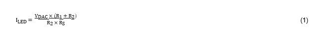
Equation 1

Figure 2-1: LED analog dimming with adjustable constant-current sink
Where:
- RS is sensing resistor
- VDAC is the DAC output voltage
- R1 and R2 are divider resistors
As the MOSFET runs in the linear mode, it can consume a lot of power resulting in low system efficiency. To solve this issue, another DAC60501 must be used to adjust the output voltage of the buck regulator (TLVM13610) and to keep the MOSFET in the linear mode close the switchon threshold (about 100-200mV above the switch-on drop voltage). The system will then run at high efficiency and lower temperature. Equation 2 shows the relationship between the output voltage of the buck regulator and the DAC60501’s output voltage.

Equation 2
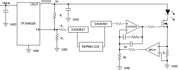
Figure 2-2: Large current LED analog dimming
Where:
- RT is the top resistor
- RB is the bottom resistor
- RC is the serial resistor with DAC
- VREF is the reference voltage of the buck regulator
- VDAC is DAC output voltage
If the maximum LED current is 20A and a 20mΩ sensing resistor is used, the sensing voltage is 0.4V and an 8W sensing resistor is required. The DAC therefore cannot use its full range, resulting in low resolution.
Furthermore, the sensing resistor dissipates a lot of power, requiring a large package.
The following modifications can solve these issues:
- Use a smaller sensing resistor (for example, with a value of only 2mΩ). Power consumed now drops to 0.8W, and the maximum sensing voltage is 0.04V
- To extend the DAC output range, insert a current-sensing amplifier (for example, the INA241A) with a gain of 100 (see Figure 2-2). This expands the DAC output to 4V from 0.04V and improves system resolution since the INA241A is a precise current-sensing amplifier with an offset of only 10μV, making it an excellent choice for this application
- Use the MSPM0L1228 as the controller to configure two DAC60501 devices with an SPI or IIC interface
- Use the TPS548D26 buck regulator with a maximum output current of 40A
Equation 3 describes the relationship between the LED current and the DAC output voltage using the options described previously.

Equation 3

Figure 2-3: LED driver using buck regulatory with dimming
Where:
- GINA241A is the gain of INA241 RS is the sensing resistor
- R1 and R2 are the divider resistors
This design can dim the LED using the analog or PWM method. In the PWM mode, high PWM frequencies can be achieved if the OPA863A is replaced by a high-speed amplifier and a highspeed DAC. Drawbacks include higher costs and a larger PCB footprint.
Drive LED with a DC/DC regulator
Figure 2-3 shows how to use a buck regulator or buck module to build an LED driver with analog dimming. The Zener diode is used to clamp the output voltage to Vz + VREF if the LED is opened. The Zener diode is removable since the maximum output voltage is equal to the input voltage in the worst case for a buck regulator; therefore, there is no danger for humans in most cases. Assume the output of the DAC is VDAC and the reference voltage of the buck regulator is VREF. Then Equation 4 shows the relationship between the LED current and the DAC voltage.

Equation 4

Figure 2-4: Dimming an LED with a simple function
According to Equation 4, the LED current is inversely proportional to the DAC voltage. To simplify the relationship, an external error amplifier can be used (see Figure 2-4), resulting in the relationship shown in Equation 5.
![]()
Equation 5
LED driver with TPS92640 OR TPS92641
TI’s TPS92640 and TPS92641 singlechip LED drivers both support analog and PWM dimming. The TPS92641 includes a shunt FET dimming input and MOSFET driver for high resolution PWM dimming. Both parts support an analog dimming ratio of 500:1. The external DAC60501 can be connected to an analog dimming terminal (IADJ) to adjust the LED current according to Equation 6.
![]()
Equation 6
This single-chip design provides the lowest cost, although its resolution is lower than the previously mentioned scheme.
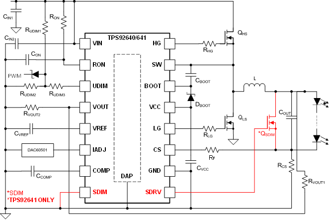
LED driver based on TPS92640 or TPS92641 with analog dimming
Summary
The previously discussed LED driver designs can meet most medical application requirements. In an actual design, designers can select one of the previously mentioned designs to meet all the specific requirements and make trade-offs between performance, cost, packaging, and so forth.
This article originally appeared in the May/June issue of Procurement Pro.